Construção do VFO com Display 2X24

Materiais
1- Placa módulo DDS SI-PROMINI
2-Arduino pro mini
3-LCD 2X24
4-Rotary encoder
5-4 pinos de 18mm
6-Barras de pinos M e F
7- Trim pots 22K
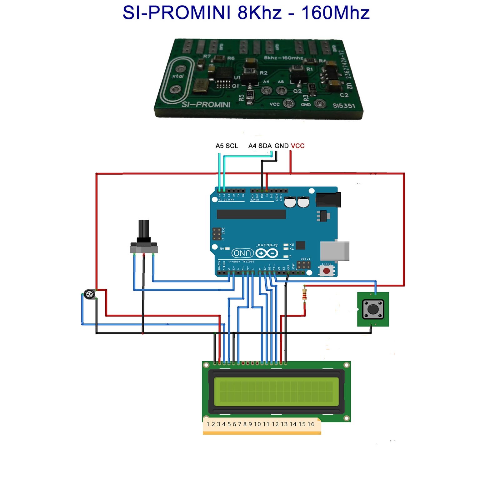
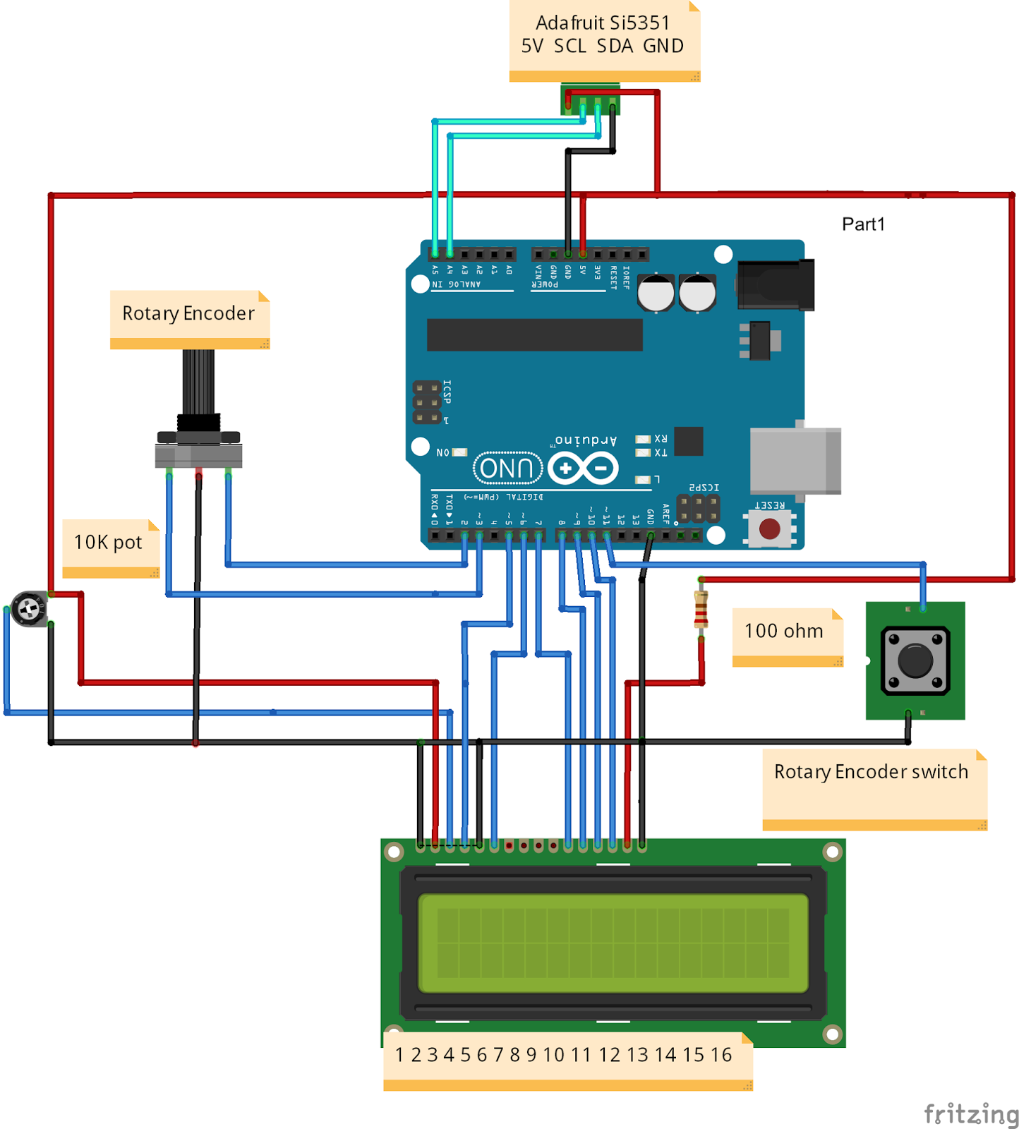
Diagrama
Exemplo no arduino uno ,mas segue a mesma configuração no pro mini.

O trim pot Foi soldado no próprio Display.